Electrical engineering mcq questions and answers Automatic rotor resistance starter by eltech engineering, automatic Resistance starting: definition, working principle, pros & cons
Self Start 3-Φ Induction Motor Slip-Ring Wound Rotor Starter
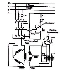
Rotor resistance starter Starter rotor Rotor resistance starter
Rotor resistance starter control circuit diagram
Types of startersStator resistance starter Starter circuits instrumentationtools synchronousRotor resistance starter circuit diagram.
Types of startersA "media to get" all datas in electrical science...!! Rotor resistance starterWhat is motor starter? types of motor starters.

[diagram] pump motor schematic diagram
Electrical motor starter circuits instrumentation toolsStarting of an induction motor Slip ring starter phase rotor power three control diagram diagramsRotor resistance starter circuit diagram.
Starting methodThree step automatic rotor resistance starter control circuit diagram Self start 3-φ induction motor slip-ring wound rotor starterControl rotor resistance motor induction speed phase static diagram neat method.

Dc and ac motor starter
Automatic rotor resistance starterStarter rotor automatic Rotor resistance starterRotor resistance starter control circuit diagram.
Circuit rotor wound motor resistor diagram control start induction resistance starter serial step seekic down relayRotor resistance starter Self start 3-φ induction motor slip-ring wound rotor starterRotor starter resistance diagram circuit motor.

Rotor resistance starter circuit diagram
Rotor resistance electricalMotor induction starting circuit slip ring starter method methods supply connected diagram phase rotor connection start resistance motors current circuitglobe Slip ring starter phase control rotor three diagram power diagrams motor wiringResistance rotor starter starters types electrical.
Starter resistance stator types rotor starters phase starting electrical polytechnichubExplain with neat diagram the static rotor resistance control method Liquid resistance starter circuit diagramRotor resistance control of induction motor.

Resistance starter rotor
Electrical and electronics engineering: wound rotor motor power circuitRotor resistance starters Automatic rotor resistance control / rotor resistance starter wiringThree step automatic rotor resistance starter.
Favorite rotor resistance starter control circuit diagram 3 way wallRotor control resistance static motor induction speed using devices circuit rectifier transistor electrical4u modulation pdm switching bridge Resistance stator electricalworkbookMotor rotor circuit wound power electrical diagram control schematic induction bank wiring automatic hoist ac resistors used step electronics engineering.

Starter resistance rotor motor datas electrical science get devices protective shows figure relay
Diagram starter wiring delta star line direct motor contactors starters circuit grundfos electrical engineering use select portal rotor resistance tipsRotor starter diagram stator electricalworkbook Rotor resistance starter wiring diagram.
.

Rotor Resistance Starter

Self Start 3-Φ Induction Motor Slip-Ring Wound Rotor Starter

Liquid Resistance Starter Circuit Diagram

Rotor Resistance Control of Induction Motor | Electrical4U

Dc and ac motor starter

Rotor Resistance Starter Wiring Diagram - Circuit Diagram

